


COPYRIGHT © 2022 COFF International Co., ltd. ALL RIGHTS RESERVED


Richtig Mischtank sizing is critical for consistent product quality, efficient mixing performance and long-term operational cost control. Engineers determine tank capacity based on process throughput, material properties and operational requirements, using standardized formulas and industry best practices. An incorrectly sized tank leads to poor mixing uniformity, wasted energy, overfilling risks and premature equipment wear.
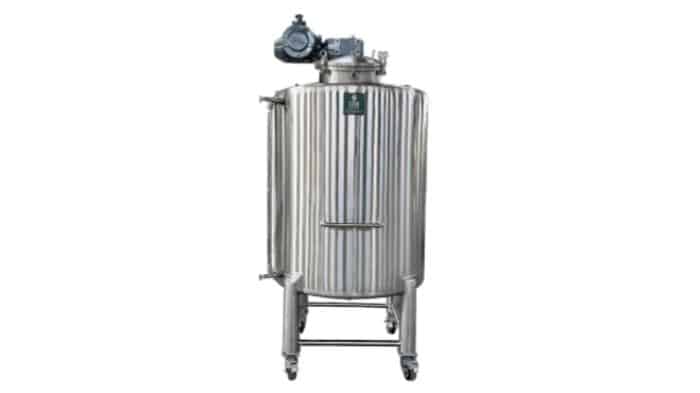
Selecting the correct mixing tank size requires evaluating material properties, production requirements, and operating conditions. Key factors include fluid viscosity, batch volume, mixing time, and safety allowances. Experienced mixing tank manufacturers can help optimize tank design for specific process needs.
Fluid properties directly influence mixing tank dimensions, agitator selection, and motor power requirements. Higher-viscosity materials create greater resistance to flow, requiring stronger mixing systems, larger impellers, and optimized tank geometry to achieve uniform mixing and prevent dead zones.
The following table shows typical mixing requirements for different industrial applications:
| Anmeldung | Typischer Kapazitätsbereich | Viscosity Range | Key Mixing Considerations |
|---|---|---|---|
| Wasseraufbereitung | 500–5,000 gallons | 1–5 cP | Large-volume circulation and standard agitation |
| Pharmaceutical Creams | 100–500 gallons | 50,000–100,000 cP | High-torque mixing and temperature control |
| Beverage Blending | 1,000–10,000 gallons | 5–50 cP | High throughput and consistent blending |
| Chemical Synthesis | 100–1,000 gallons | Variabel | Corrosion resistance and process control |
| Paint Production | 200–2,000 gallons | 100–50,000 cP | High-shear dispersion and strong agitation |
For high-viscosity products, tank sizing must consider not only working volume but also mixing power, impeller diameter, and heat transfer requirements.
Required tank capacity is mainly determined by production volume and process flow.
Common mixing tank capacities include:
| Tank Size Category | Typical Volume Range | Common Applications |
|---|---|---|
| Klein | 1–1,000 L | Laboratory testing, R&D, pilot production |
| Mittel | 1,000–10,000 L | Food & beverage, cosmetics, specialty chemicals |
| Groß | 10,000 L+ | Bulk production, water treatment, continuous processing |
Actual tank size should be determined based on process requirements rather than volume alone.
Adequate headspace is an essential part of mixing tank design. The maximum operating fill level must account for changes during operation, including:
Proper headspace prevents overflow, improves operating safety, and helps maintain reliable performance of the tank and mixer assembly.
Working volume is the actual liquid volume that will be mixed during normal operation. The calculation method depends on your process type:
Example calculation:
For a continuous process with a 20 L/min inlet flow and a required 30-minute hold time:
V = 20 L/min × 30 min = 600 L working volume
Tanks are never filled to the very top. Convert working volume to total tank volume by applying a fill factor:
Using the example above: with a 600 L working volume and a 70% target fill level, total tank capacity should be approximately 850–900 L. Always round up to the nearest standard tank size for practicality.
Tank size alone does not guarantee good mixing. Match the mixer and impeller to your tank dimensions:
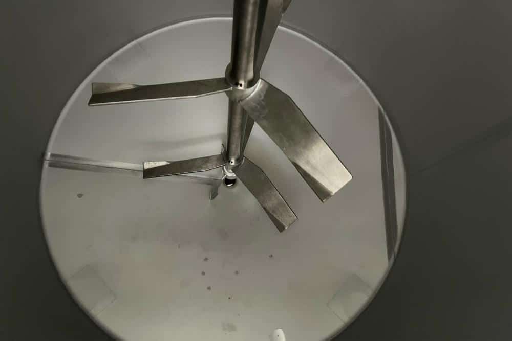
The D/T (impeller diameter / tank diameter) ratio is a core design parameter:
In unbaffled tanks, offset impeller mounting reduces vortexing and improves mixing. For jet mixers, a 30°–45° mounting angle delivers the best circulation.
Baffles eliminate surface vortices and convert rotational flow into vertical circulation, greatly improving mixing uniformity. They do increase power draw slightly, so motor sizing must account for their presence. Proper outlet placement also prevents short-circuiting and ensures all fluid passes through the mixing zone.
Motor power is sized based on tank volume, fluid viscosity and required mixing intensity. Low-viscosity blending requires less power per unit volume, while high-shear dispersion and high-viscosity mixing demand significantly more motor capacity.
Sanitary applications such as food, beverage and pharma also require CIP (clean-in-place) systems, spray balls and polished stainless steel interiors, all of which must be factored into the initial tank design.
Sizing a mixing tank is a balance of process requirements, fluid properties and mechanical design. Start by defining your required working volume based on batch size or continuous flow and residence time, then add appropriate safety headspace to get total tank capacity.
Always match impeller size and motor power to your fluid viscosity and tank dimensions, and build in room for future production growth to maximize long-term value. Working with an experienced tank manufacturer will help you avoid common sizing mistakes and ensure reliable, consistent mixing performance.
Working volume is the actual liquid volume used during normal mixing operation. Tanks are typically filled to 60–80% of their total capacity, leaving headspace to prevent overflow and accommodate foaming or thermal expansion.
Higher viscosity increases fluid resistance, requiring larger impellers, more powerful motors and sometimes adjusted tank geometry to maintain proper circulation. Very high-viscosity products often need larger working volumes for adequate mixing time.
For most general mixing applications, an impeller diameter equal to roughly 1/3 of the tank’s inner diameter delivers the most efficient performance. Acceptable ratios range from 1/5 to 3/5 depending on viscosity and mixing goal.
A standard safety margin is 20–40% of working volume, meaning the tank is filled to 60–80% of total capacity. Processes with high foaming or agitation need a larger margin.
Stainless steel 304 and 316L are the most common for food, pharmaceutical and chemical applications. Carbon steel with epoxy lining is used for paints and industrial fluids. Material selection is based on fluid chemistry and sanitation requirements.